Research update / Momentum Exchange Banks
Opposed reels.
A better connection.
An orbital port needs more than a large flywheel. It needs a way to meet a ship, attach to it, make a controlled pull, and let go. The latest work separates those jobs into machines we can start to analyze.
The current direction: two independently driven annular drum rings, wound in opposite directions; two main load ribbons; and a small pilot carrying a 300-meter local leader. The pilot establishes the first connection. The principal capture assembly carries the main pull.
Start with a small connection.
The principal capture head approaches with its motion already nearly matched to the ship. A small maneuvering pilot carries a short leader to an initial latch point. The leader and local thrusters guide the head into alignment; dampers absorb the remaining closing motion. Structural attachments then distribute the main ribbon loads into the payload.
Keeping the leader local removes an earlier bank-to-payload pilot line that stretched across the whole encounter. A 300-meter handling line has a different job from the main ribbons, which can extend hundreds of kilometers.
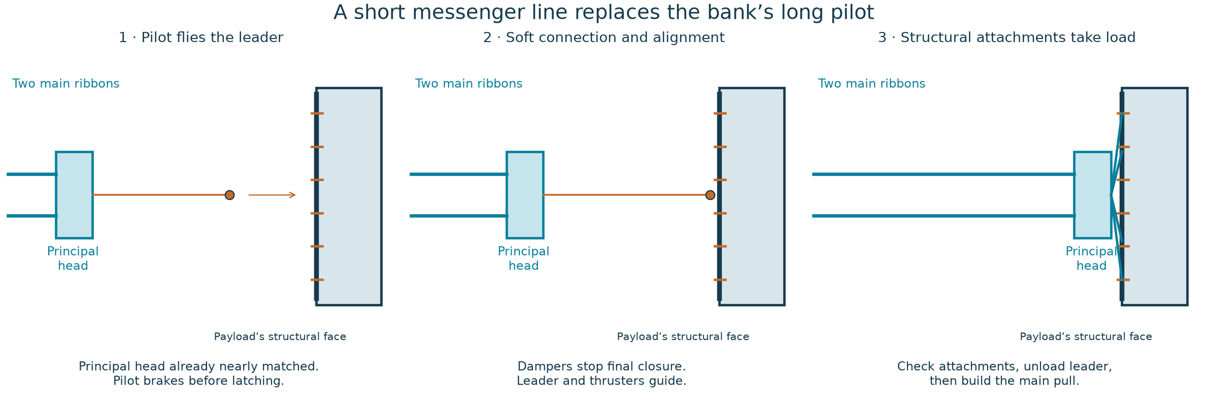
One illustrative contact calculation uses a 20-ton capture head approaching a 10,000-ton payload at 5 m/s. With 8 meters of working damper travel, the free two-body case absorbs about 250 kJ with 31 kN of net resistance over 3.2 seconds. That is the compression phase after contact, not the time for the entire docking operation. Main-ribbon loads must be low during this phase.
A winch pulling inward during compression adds work for the dampers to absorb. The leader guides the connection; it should not fight the braking system. Head mass, reserve ribbon, fittings, and release hardware still need a complete installed mass budget.
Let the reels do the heavy work.
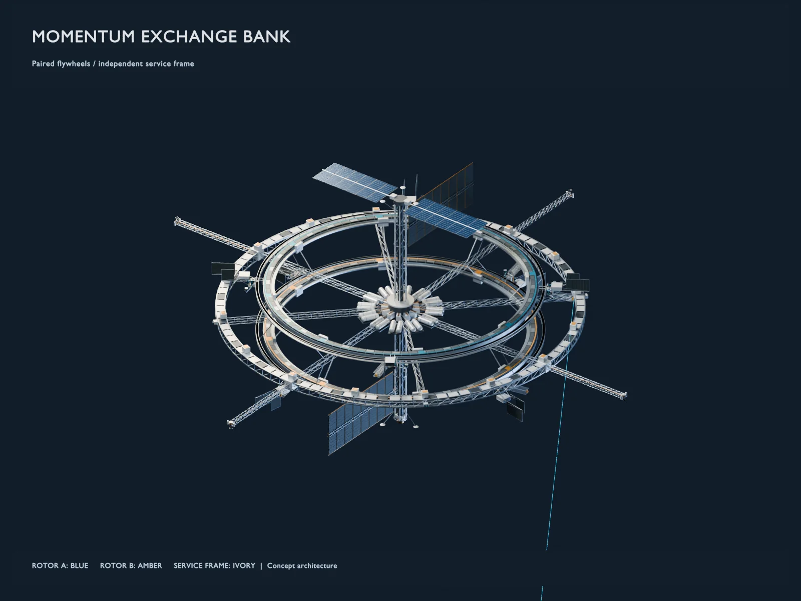
The preferred arrangement uses opposite winding directions on a pair of independent annular drums, with stationary motor windings on the service structure. Their modeled motor reactions largely cancel during a balanced pull. That does not cancel the bank’s orbital recoil or settle every source of torque.
In the reference model, each ring has a 2,150-meter winding radius, an assumed bare mass of 10,000 tons, and 50 km of retained ribbon at the start. The ribbons use an assumed 1 GPa working stress. The bank’s total mass is 100 million tons and it is free to recoil. These are inputs to a design study, not specifications for available machinery.
A turn is a meaningful maneuver.
The faster modeled encounter starts with a 10,000-ton payload moving at 1 km/s relative to the bank, at a 1,000 km encounter radius. After about 405 seconds, the payload leaves with its velocity vector turned roughly 23 degrees. Its speed in the bank’s initial rest frame is about 1 m/s lower.
That produces a vector velocity change of about 398 m/s. Most of the change is direction. It should not be read as a 398 m/s speed boost.
| Quantity | Modeled result |
|---|---|
| Time from attached start to release | 405.15 seconds |
| Vector velocity change | 397.58 m/s |
| Change in speed | −1.04 m/s |
| Peak ribbon load at a ring | 32.13 MN |
| Peak motor demand, worst ring | 199.70 MW |
| Peak regeneration, worst ring | 290.13 MW |
| Deployed main-ribbon mass, each | 48,343.88 tons |
Motor demand and regeneration peak at different times. These are mechanical powers before electrical conversion and auxiliary loads. The bank-end ribbon load includes the dynamics of the massive ribbon; it is not the force applied at each payload attachment.
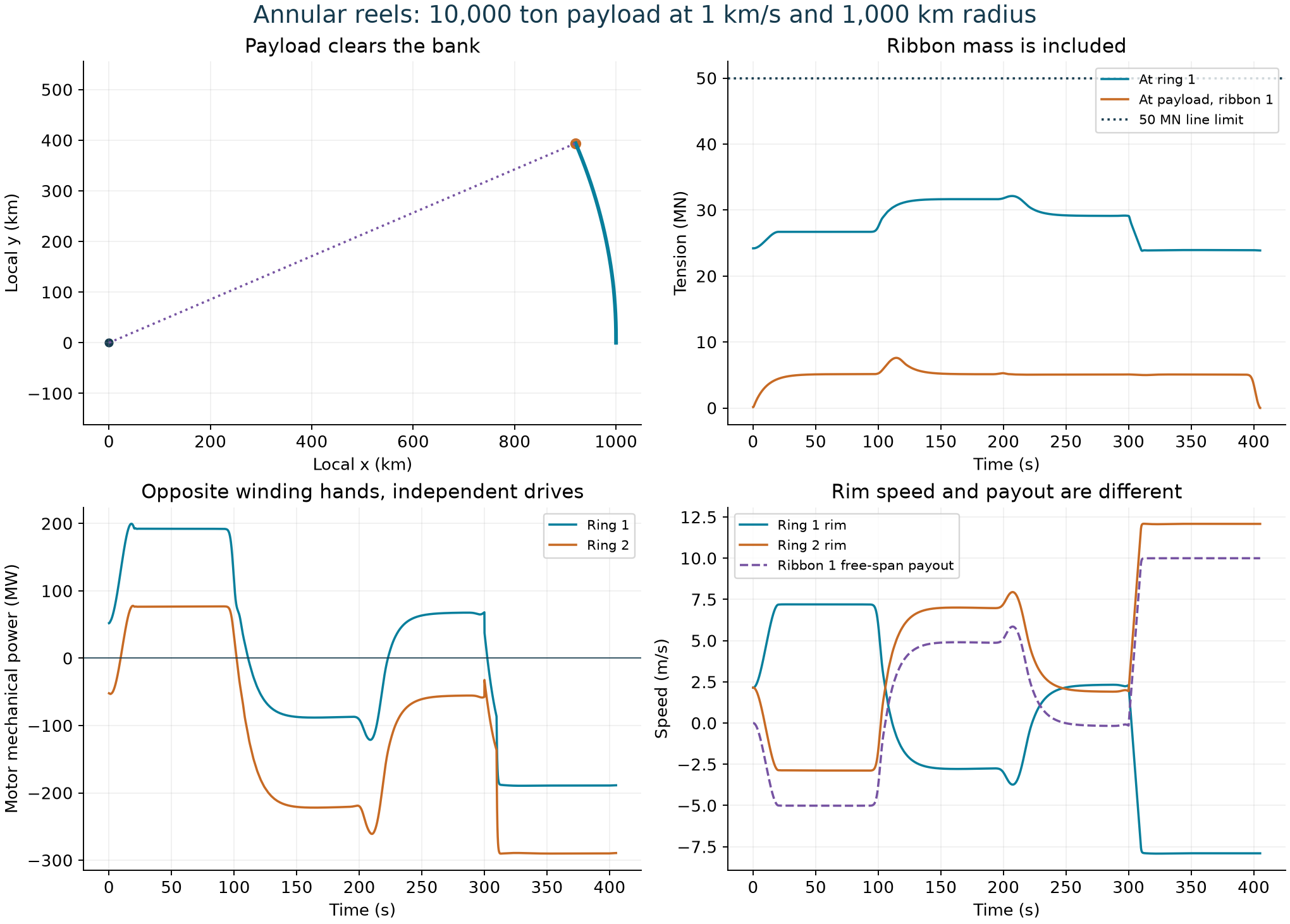
The model begins unloading at 300 seconds and waits until both ribbon tips carry at most 50 kN before release. Scheduling matters: with the assumed material properties, an axial disturbance takes about 98.5 seconds to travel one way along a 1,000 km ribbon. A controller at the head can react locally, but it cannot make a mechanical change arrive instantly from the bank.
What the model answers—and what comes next.
The encounter simulation starts after hard attachment. It investigates the coupled motion of the payload, ribbons, reels, and recoiling bank over a short exchange. It does not yet simulate the soft capture, detailed latch release, ribbon twist, or collisions against the actual 3D machinery.
The short payout approximation keeps node masses and stored-ring inertia fixed. By release, the omitted material transport is about 0.11% of deployed ribbon mass and 0.42% of ring inventory mass. Full deployment and recovery need a model that transports that material explicitly.
The next steps are to connect the capture and release hardware to the flexible-ribbon simulation, update the machine geometry, and develop the thermal, structural, recovery, and operating budgets. A usable transport network also needs solved trajectories, traffic planning, and a way to restore the bank’s orbit.
Adapted from “MEB — Opposed reels and rapid local capture,” Galen Matson’s October 2, 2026 design analysis. Figures are from the associated local research project. This update describes an evolving proposal.